|
DirectXGraphics:
Stencil Buffer Tricks
Author:
Jack Hoxley
Written: 21st July 2002
Contact: [EMail]
Download: Stencil
Buffers.Zip (78kb)
Contents
of this lesson
1. What is the stencil buffer?
2. A simple example: Draw depth complexity
1.
What is the stencil buffer?
The stencil
buffer is part of the memory space used by the
Z-Buffer in the Direct3D flipping chain. It allows
you to set a "hidden" value for each
pixel rendered, and/or determine what pixels get
rendered based on the contents of the buffer at
the given coordinate. Essentially it operates as a
stencil-template for future rendering...
You should be
familiar with the Z buffer by now, and should
therefore be aware that you specify the Z buffer
resolution as the number of bits of memory per
pixel it uses - 16, 24 or 32. when using either 16
or 32 bit modes the z buffer occupies an amount of
memory equal to 2 or 4 bytes (with no spare). When
using 24bit mode there is 8bits of unused memory
(to pad it out to a more convenient 32bit/4byte
boundary). It is in this unused 8bits that we can
store the stencil buffer data.
There are two
formats available in D3D8 - 24bit Z and 8bit
Stencil OR 24bit Z and 4bit Stencil (4bits
unused). In order to make use of the stencil
buffer you must check to see if the device
supports either of these formats. The majority of
modern hardware (GeForce and above) will support
stencil buffers, but support on older cards is
very sketchy at best.
Once we know we
can use the stencil buffer we need to make use of
a very important equation:
(StencilRef
And StencilMask) CompFunc (StencilBufferValue
And StencilMask)
There are 4
components to this equation:
1. StencilRef - a reference value you can
use for comparisons
2. StencilMask - used so you can focus on
particular bits of accuracy (say you only need the
3rd bit)
3. CompFunc - very important, this
essentially defines what and how a pixel can pass
a stencil test.
4. StencilBufferValue - This is the value
currently stored in the stencil buffer.
The first 3 in
the list can be configured using
Direct3DDevice8.SetRenderState( ) calls.
Stencil Buffer
'tricks' can be very useful in creating some of
the more advanced special effects you see in
industrial-quality 3D games currently. Shadows,
Reflections, Sniper-zooms, heat-sensing
displays... You can also use them for more subtle
effects such as screen dissolves, non-rectangular
rendering (render to an oval-shaped view for
example).
2. A simple example: Draw depth complexity
First off, what
is depth complexity? sometimes referred to as
'Overdraw' it is essentially a count of the number
of times each pixel is drawn each frame. In theory
this should only be one - why would you want to
draw a pixel two, three or four times? if you
think about it - each time you render a triangle
it is compared with the depth buffer and only
rendered if is in front of whatever is already
there - BUT it doesn't know if anything later in
the frame will be in front of it (hence obscuring
it from our view). It is this method that means
that in a complex scene it is quite possible that
each pixel will be rendered more than once.
The
following code is a rather simple use of the depth
buffer, and doesn't really serve much use in a
real-world application. But it's a useful example
for learning about the stencil buffer. The source
code presented is intended to be plugged into the
standard framework presented in my tutorials, if
you're unfamiliar with this you'll need to
download it.
The
first step is to enumerate for stencil buffer
support. This can be done using this simple logic
tree. The end result is that the 'D3DWindow'
structure is filled appropriately (and then the
device is created) or the sample will exit:
If
D3D.CheckDepthStencilMatch(0, D3DDEVTYPE_HAL,
_
DispMode.Format,
DispMode.Format, _
D3DFMT_D24S8) = D3D_OK
Then
'we can use the D24/S8 format
D3DWindow.AutoDepthStencilFormat = D3DFMT_D24S8
Else
If D3D.CheckDepthStencilMatch(0, D3DDEVTYPE_HAL,
_
DispMode.Format,
DispMode.Format, _
D3DFMT_D24X4S4) = D3D_OK
Then
'we can use the D24/S4 format
D3DWindow.AutoDepthStencilFormat = D3DFMT_D24X4S4
Else
'we cant use either stencil format... oh well.
Unload
Me
End
End If
End If |
|
|
|
The
above code must be executed before the
CreateDevice() call, or the results are
meaningless! The next change comes in the Render(
) function - in particular the part where we clear
the buffers. Now that we're using the stencil
buffer we must also clear it each frame:
D3DDevice.Clear 0,
ByVal 0, D3DCLEAR_TARGET
Or _
D3DCLEAR_ZBUFFER Or _
D3DCLEAR_STENCIL, _
D3DColorXRGB(200, 200, 255), _
1#, 0 |
|
|
|
Not
a particularly complicated change that one...
However, this next one is a little tricky. In
order to display the depth complexity of a scene
you have to first render the scene and update the
stencil buffer; you then need to re-render the
scene with a set of full-screen quads to display
the contents of the stencil buffer. It is useful
to note that the first-pass (with the normal
objects) won't actually be seen on screen -
therefore there is no point in rendering anything
but the raw geometry; lights, textures, pixel
shaders etc... won't be seen and are therefore a
complete waste of time :-)
This
next piece of code shows you how to configure the
stencil buffer for the first pass:
Private Sub
SetupStencilBuffer()
With D3DDevice
.SetRenderState D3DRS_STENCILENABLE, 1
.SetRenderState D3DRS_STENCILFUNC, D3DCMP_ALWAYS
.SetRenderState D3DRS_STENCILREF, 0
.SetRenderState D3DRS_STENCILMASK, 0
.SetRenderState D3DRS_STENCILWRITEMASK, &HFFFFFFFF
.SetRenderState D3DRS_STENCILZFAIL, D3DSTENCILOP_INCRSAT
.SetRenderState D3DRS_STENCILFAIL, D3DSTENCILOP_KEEP
.SetRenderState D3DRS_STENCILPASS, D3DSTENCILOP_INCRSAT
End With
End Sub |
|
|
|
The above code
looks far more complex than it really is. The
first two lines deal with turning on the stencil
buffer and setting it so that all tests always
pass. To display overdraw we don't need a
reference or mask value, so we leave them as 0.
The last three lines are the most important
really, D3DSTENCILOP_INCRSAT
indicates that we'll increment the current value
in the buffer but STOP when we've reached the
maximum value (15 or 255 depending on the bit
depth). D3DSTENCILOP_INCR would also increment the
value in the buffer, but when it reaches the
maximum value it would wrap back to 0 - which we
don't want. The last three lines are used to tell
D3D what it should do to the values in the buffer
depending on what the outcome of the various tests
were.
After
rendering the geometry with these stencil buffer
settings we can go about displaying the final
overdraw values. Consider that the stencil buffer
now contains a complete set of values indicating
how many times each pixel was drawn to. In order
to display this we need to re-configure the device
to ONLY render on a given value. This basically
means reading the stencil buffer, but not actually
writing to it.
Private Sub RenderOverDraw()
Dim TLVerts(0
To 3)
As TLVERTEX
'//needed to size the quad properly.
Dim VP
As D3DVIEWPORT8
D3DDevice.GetViewport VP
'//set up the default parameters for the TL Quad. The colour will
'//be altered for each level we draw.
TLVerts(0).rhw = 1: TLVerts(1).rhw = 1: TLVerts(2).rhw = 1: TLVerts(3).rhw = 1
TLVerts(0).Color = D3DColorXRGB(255, 0, 0)
TLVerts(1).Color = TLVerts(0).Color
TLVerts(2).Color = TLVerts(0).Color
TLVerts(3).Color = TLVerts(0).Color
TLVerts(0).X = 0: TLVerts(0).Y = 0
TLVerts(1).X = VP.Width: TLVerts(1).Y = 0
TLVerts(2).X = 0: TLVerts(2).Y = VP.Height
TLVerts(3).X = VP.Width: TLVerts(3).Y = VP.Height
D3DDevice.SetTexture 0,
Nothing
D3DDevice.SetVertexShader FVF_TLVERTEX
'//This next line is necessary to clear any pixels with
'//a 0 overdraw value... as they wont be picked up in the next
'//stage.
D3DDevice.Clear 0, ByVal 0, D3DCLEAR_TARGET, 0, 0, 0
With D3DDevice
If bWire
Then .SetRenderState D3DRS_FILLMODE, D3DFILL_SOLID
'//we dont care whats in the z buffer, so ignore it.
.SetRenderState D3DRS_ZENABLE, 0
.SetRenderState D3DRS_STENCILZFAIL, D3DSTENCILOP_KEEP
.SetRenderState D3DRS_STENCILFAIL, D3DSTENCILOP_KEEP
.SetRenderState D3DRS_STENCILPASS, D3DSTENCILOP_KEEP
.SetRenderState D3DRS_STENCILFUNC, D3DCMP_NOTEQUAL
.SetRenderState D3DRS_STENCILREF, 0
'DRAW LEVEL 1 OVERDRAW
.SetRenderState D3DRS_STENCILMASK, &H1
TLVerts(0).Color = D3DColorXRGB(0, 0, 255)
TLVerts(1).Color = TLVerts(0).Color
TLVerts(2).Color = TLVerts(0).Color
TLVerts(3).Color = TLVerts(0).Color
.DrawPrimitiveUP D3DPT_TRIANGLESTRIP, 2, TLVerts(0), Len(TLVerts(0))
'DRAW LEVEL 2 OVERDRAW
.SetRenderState D3DRS_STENCILMASK, &H2
TLVerts(0).Color = D3DColorXRGB(0, 255, 0)
TLVerts(1).Color = TLVerts(0).Color
TLVerts(2).Color = TLVerts(0).Color
TLVerts(3).Color = TLVerts(0).Color
.DrawPrimitiveUP D3DPT_TRIANGLESTRIP, 2, TLVerts(0), Len(TLVerts(0))
'DRAW LEVEL 3 OVERDRAW
.SetRenderState D3DRS_STENCILMASK, &H4
TLVerts(0).Color = D3DColorXRGB(255, 128, 0)
TLVerts(1).Color = TLVerts(0).Color
TLVerts(2).Color = TLVerts(0).Color
TLVerts(3).Color = TLVerts(0).Color
.DrawPrimitiveUP D3DPT_TRIANGLESTRIP, 2, TLVerts(0), Len(TLVerts(0))
'DRAW LEVEL 4 OVERDRAW
.SetRenderState D3DRS_STENCILMASK, &H8
TLVerts(0).Color = D3DColorXRGB(255, 0, 0)
TLVerts(1).Color = TLVerts(0).Color
TLVerts(2).Color = TLVerts(0).Color
TLVerts(3).Color = TLVerts(0).Color
.DrawPrimitiveUP D3DPT_TRIANGLESTRIP, 2, TLVerts(0), Len(TLVerts(0))
'DRAW ALL REMAINING LEVELS OVERDRAW
'(this level wont exist for a 4bit stencil buffer)
.SetRenderState D3DRS_STENCILMASK, &HF0
TLVerts(0).Color = D3DColorXRGB(255, 255, 255)
TLVerts(1).Color = TLVerts(0).Color
TLVerts(2).Color = TLVerts(0).Color
TLVerts(3).Color = TLVerts(0).Color
.DrawPrimitiveUP D3DPT_TRIANGLESTRIP, 2, TLVerts(0), Len(TLVerts(0))
'restore the various stage states...
.SetRenderState D3DRS_ZENABLE, 1
.SetRenderState D3DRS_STENCILENABLE, 0
End With
End Sub |
|
|
|
There's a lot of
code in that table, but the majority of it is
quite simple - you should all be familiar with the
TLVerts( ) configuration and rendering code by
now! For each layer all we need to do is change
the stencil mask value - accending in powers of 2:
1,2,4,8 (1st, 2nd, 3rd and 4th bits respectively).
D3D will handle the rest... we attempt to render
the quad over the entire screen, but D3D will only
actually render a pixel when it passes the stencil
test - in this case, when the overdraw is of the
correct value.
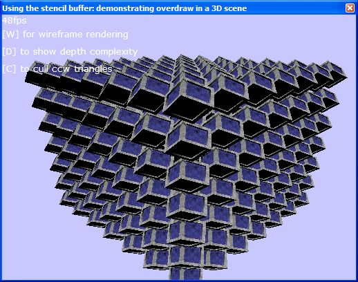
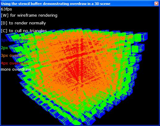
The following two
images are from the sample program. The first is
of normal rendering - not very representative of a
real game environment, but a good demonstration of
overdraw. The second is showing the scenes
overdraw.


As
you can see from the second image, overdraw
follows an almost radial pattern - only the middle
shows the highest overdraw. This is fairly logical
- because of the way that the scene is rendered
(camera POV) the majority of cubes are clustered
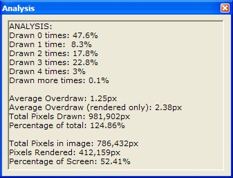
around the center of the image. The next
screenshot shows the output of a simple analysis
program I made that will process a screenshot and
calculate overdraw values:

|

