|
Immediate
Mode: Basics
By: Carl Warwick [Email]
[Web: Freeride Designs]
Written: June 16 2000
Download:
IM_Basics.Zip
(7kb)
Contents
Introduction
This is my first tutorial of many on using Direct
3D Immediate Mode (DirectX 7) using Visual Basic. If you are new to DirectX
programming then I would suggest that you check out some DDraw tutorials before
venturing into the world of 3D.
In this tutorial we are first going to initialise
DDraw and D3DIM in fullscreen, exclusive mode, if you are used to using DDraw
then you'll have a bit of a headstart but I'll try and explain what everything
does. The reason we need DDraw is because D3DIM renders everything to a DDraw
surface, this surface will usually be the backbuffer. Then we enter the main
loop, this is where our main game code would go, but for this tutorial all we'll
do is clear the screen to black and draw a rotating square with a different
color at each corner.

Before
the code
Before we start programming I'm going to try
and explain some of the basics of D3DIM.
Vertices - Vertices (plural of Vertex) are the corners
or points that you define to make up your object, a flat square has 4 vertices,
and a cube has 8 vertices etc. In D3D there are 3 different types of vertex,
you can also create your own vertex type, but with the 3 you've got there isn't
really much point. Here's an explanation of the 3 vertex types:
- D3DTLVertex - TL stands for
Transformed and lit, which means YOU have to transform the co-ordinates to
screen space, and YOU are responsible for lighting the vertex. You can also
specify the tu and tv values which are the texture co-ordinates, but we'll
talk about these in another tutorial.
- D3DLVertex - L stands for
lit, this means that you specify the co-ordinates of the vertex in worldspace
and D3D will convert it to screen space for you, but you still have to light
the vertex yourself.
- D3DVertex - This vertex type
also requires you to specify the co-ordinates in worldspace, but you also
have to specify the vertex normal so that D3D can light the vertex for you.
I'll cover what a normal is in another tutorial, so don't worry about it for
now.
In this tutorial we will cover
the D3DTLVertex.
Space - I've mentioned screen and world space
so if you don't know the difference then I'll describe them here.
Screen space is the co-ordinates that you see on the screen, (0, 0) is the top-left
corner, and (screen width, screen height) is at the bottom-right corner.
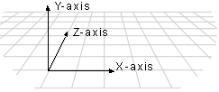
World space is defined by 3 co-ordinates (x, y, z), there are many ways of arranging
these, but in D3D the left-hand co-ordinate system is used. Its probably easier
to imagine it from a picture, so here it is.

That's probably enough for now, I'll explain
any more concepts when we get to them.
Declarations
Finally, we start coding.
Our project will have 1 form "frmMain", and 1 module "modMain".
All our declarations will go in "modMain".
Option
Explicit
Public
DX As
DirectX7 'Direct X
Public
DD As
DirectDraw7 'Direct Draw
Public
Primary
As
DirectDrawSurface7 'Primary surface
Public
BackBuffer
As
DirectDrawSurface7 'Backbuffer
Public
Direct3D
As
Direct3D7 'Direct 3D
Public
Device
As
Direct3DDevice7 'Direct 3D Device
Public
TLVertexList(3)
As
D3DTLVERTEX 'Array of vertices (TL = Transformed and Lit)
Public
bRunning
As
Boolean 'Boolean to check if program is still running
Public
Const
pi =
3.14 'Constant to hold the value of pi
Public
Const
Rad =
pi /
180 'multiply degrees by Rad to get angle in radians |
|
|
|
These are the basic declarations that you will
use time and time again in your D3D projects, the primary and backbuffer are
of the DirectDrawSurface7 type, and will be used for rendering to and displaying
the scene.
We then declare TLVertexList(3), this is an array used to store the data of
the four corners of our square.
bRunning is a simple boolean that is true whilst the program is running and
then set to false if a key is pressed so that we can exit the program.
Initialisation
The first part of the code that is called is
"Sub Main" which is inside "modMain", so its from here that
we will call our initialisation and main_loop routines. We pass the values "640",
"480" and "16" to our initialisation routine, these are
just values that specify the screen width, height and color depth, and can be
changed to suit your needs.
Private
Sub
Main()
frmMain.Show
'Initialize DirectX with screen 640x480x16
Call
Initialize_DX(640,
480,
16)
'Start the main loop
bRunning
= True
Call
Main_Loop
'End the program and return to your normal life
Call
Endit
End
Sub |
|
|
|
The initialisation routine is a bit more complicated.
Public
Sub
Initialize_DX(Optional
Width
As
Integer
= 640,
Optional
Height
As
Integer
= 480,
Optional
BPP As
Byte =
16)
Dim
ddsd
As
DDSURFACEDESC2
Dim
caps
As
DDSCAPS2
Dim
DEnum
As
Direct3DEnumDevices
Dim
Guid
As
String
'Create the DirectDraw object and set the application
'cooperative level.
Set DX
= New
DirectX7
Set DD
=
DX.DirectDrawCreate("")
'Make a fullscreen, exclusive application
DD.SetCooperativeLevel
frmMain.hWnd,
DDSCL_EXCLUSIVE
Or
DDSCL_FULLSCREEN
Or
DDSCL_ALLOWREBOOT
DD.SetDisplayMode
Width,
Height,
BPP,
0,
DDSDM_DEFAULT
'Prepare and create the primary surface.
ddsd.lFlags
=
DDSD_BACKBUFFERCOUNT
Or
DDSD_CAPS
ddsd.ddsCaps.lCaps
=
DDSCAPS_COMPLEX
Or
DDSCAPS_FLIP
Or
DDSCAPS_3DDEVICE
Or
DDSCAPS_PRIMARYSURFACE
ddsd.lBackBufferCount
= 1
Set
Primary
=
DD.CreateSurface(ddsd)
'Attach the backbuffer. the DDSCAPS_3DDEVICE tells the
'backbuffer that its to be used for 3D stuff
caps.lCaps
=
DDSCAPS_BACKBUFFER
Or
DDSCAPS_3DDEVICE
Set
BackBuffer
=
Primary.GetAttachedSurface(caps)
Set
Direct3D
=
DD.GetDirect3D
'Get the last device driver (last one is usually the best one)
'you could specify or search for a particular device, eg
RGB or HAL device
Set
DEnum
=
Direct3D.GetDevicesEnum
Guid =
DEnum.GetGuid(DEnum.GetCount)
'Set the Device
Set
Device
=
Direct3D.CreateDevice(Guid,
BackBuffer)
End
Sub |
|
|
|
Firstly we create a new DirectX7 object, and
then create our DDraw object.
Then we create a fullscreen and exclusive application, and then set the display
mode to the passed variables.
Next we create our primary surface, and tell it that it will have 1 backbuffer
that is to be flipped, we also tell it that its to be used for 3D operations
(DDSCAPS_3DDEVICE). Then we attach a backbuffer to the primary surface.
Now we create our D3DIM object. Then we need to find a device to use, so we
fill DEnum with all the different devices information, then we set Guid (a string)
to hold the Guid of the last device that was found, the reason for using the
last device is because in most cases its the best one. Finally we create our
device using the Guid that we just found.
Main
Loop
Now lets take a look at our Main_Loop.
Public
Sub
Main_Loop()
Dim
stepval
As
Integer
'Start our loop, press the 'Esc' key to exit
Do
Until
bRunning
=
False
'decrease stepval by 1 to rotate the rectangle clockwise
'If stepval is less than 0
degrees then make stepval = 360 degrees
stepval
=
stepval
- 1
If
stepval
<=
0 Then
stepval
= 360
'Create the four vertices (corners) of the square
Call
DX.CreateD3DTLVertex(320
+
Sin(stepval
* Rad)
* 50,
240 +
Cos(stepval
* Rad)
* 50,
0, _
1,
DX.CreateColorRGB(1,
0, 0),
1, 0,
0,
TLVertexList(0))
Call
DX.CreateD3DTLVertex(320
+
Sin((stepval
- 90)
* Rad)
* 50,
240 +
Cos((stepval
- 90)
* Rad)
* 50,
0, _
1,
DX.CreateColorRGB(0,
1, 0),
1, 0,
0,
TLVertexList(1))
Call
DX.CreateD3DTLVertex(320
+
Sin((stepval
+ 90)
* Rad)
* 50,
240 +
Cos((stepval
+ 90)
* Rad)
* 50,
0, _
1,
DX.CreateColorRGB(0,
0, 1),
1, 0,
0,
TLVertexList(2))
Call
DX.CreateD3DTLVertex(320
+
Sin((stepval
+ 180)
* Rad)
* 50,
240 +
Cos((stepval
+ 180)
* Rad)
* 50,
0, _
1,
DX.CreateColorRGB(1,
1, 0),
1, 0,
0,
TLVertexList(3))
'Clear the device AFTER all the changes to any vertices, and
BEFORE
'calling Device.BeginScene
and any bltting.
Call
Clear_Device
'Begin the scene, must do this after Calling Clear_Device, and
before
'calling Blt3D()
Device.BeginScene
'Render the rectangle to the device (backbuffer)
Call
Device.DrawPrimitive(D3DPT_TRIANGLESTRIP,
D3DFVF_TLVERTEX,
TLVertexList(0),
4,
D3DDP_WAIT)
'Call EndScene when finished using D3D routines
Device.EndScene
'Flip the primary surface to display the scene
Primary.Flip
Nothing,
DDFLIP_WAIT
'Let windows do its stuff
DoEvents
Loop
End
Sub |
|
|
|
Its all pretty straight forward until we get
to this line:
Call DX.CreateD3DTLVertex(sx, sy, sz, rhw, color, specular,
tu, tv, v)
So we'll examine it in a bit more detail here. I'll explain all the passed values:
- sx, sy, sz - The first 3 variables are the
positions on screen that the D3DTLVertex is to be displayed, sx and sy are
simply the screen space positions, but sz is the depth of the vertex, this
would usually be set to 0, but if a Z-buffer is attached then sz can be used
to specify what order everything should be displayed in, and should always
be in the range of 0 to 1. For now just set it to 0
- rhw - As far as I can tell this is useless,
and should just be set to 1.
- color, specular - The color of our vertex,
used to simulate lighting on the vertex. The color is interpolated (blended)
between vertices.
- tu, tv - The texture co-ordinates, these will
be explained in another tutorial.
- v - is the vertex that we are changing.
Unless you are familiar with trigonometry then you are probably confused by how I position the 4 vertices,
so lets examine this a bit more. We set the sx value of the second vertex at
320 + Sin((stepval - 90) * Rad) * 50,
the number 320 is just the horizontal position for the centre of our square.
Now comes the bit of trigonometry,
we use Sin to get horizontal positions, and Cos to get the vertical positions (offset from center).
stepval is the angle in degrees that the square is rotated by, and as we all know a complete circle has 360 degrees, so to get the correct position for each vertex we need to alter the rotated angle by a set number,
in this case its -90 because we want this vertex to be 90 degrees further clockwise than our first vertex.
Then you multiply the angle by our constant 'Rad', this is because VB uses radians to specify angles rather than degrees.
Finally we have to multiply our value returned by the Sin or Cos function by the value 50, this is the distance from the center point that our vertex will be,
so increase this number to make a bigger square or decrease it to make it smaller, but all vertices need to be multiplied by the same number otherwise it will look very strange.
Of course if we didn't want to rotate the square then we could just specify the exact screen coordinates that we want to position the square at. But I included the rotation example because its something that I get asked about alot.
Now we must clear the device, this is done before
any rendering can be done, this is a very simple routine, and you should look
at the downloadable source to see how it works.
Next we call DrawPrimative to render our square to the screen:
Call Device.DrawPrimitive(D3DPT_TRIANGLESTRIP,
D3DFVF_TLVERTEX, TLVertexList(0), 4, D3DDP_WAIT)
Your probably thinking
"What on earth does all this mean", well I'll explain
- D3DPT_TRIANGLESTRIP
- This tells the device that our vertices are in a specific order, in this
case a triangle strip. (Please refer to "Primitive Types" below)
- D3DFVF_TLVERTEX - This tells the device what format our vertices are
in, in this case we are using the TLVertex, but a combination of flags can
be used to define you own vertex type. FVF stands for Flexible vertex format.
- TLVertexList(0) - The first element in an array of vertices that are
to be rendered.
- 4 -
The number of vertices in the array to be rendered.
- D3DDP_WAIT - The type of rendering to be used, your probably better off using
D3DDP_DEFAULT, because WAIT is mainly used for debugging, but you won't noticed
much difference.
Primitive
Types
You can't just pass an array of vertices to D3D
and expect it to know how they are arranged, to solve this you have to pass
a constant in the form of D3DPT_*** along with your vertices, this constant
describes the way your vertices are arranged. Here's a description of each type:
- D3DPT_POINTLIST - Renders the vertices as
a list of isolated points
- D3DPT_LINELIST - Renders the vertices as a
list of isolated lines, there must be more than 2, and an even number of vertices
for this call.
- D3DPT_LINESTRIP - Renders vertices as a continuous
line.
- D3DPT_TRIANGLELIST - Renders the vertices
as isolated triangles, each group of 3 vertices represents a different triangle,
there must be a multiple of 3 vertices in the array for this call.
- D3DPT_TRIANGLESTRIP - Renders a series of
connected triangles (As in the diagram).

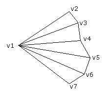
- D3DPT_TRIANGLEFAN - Renders a series of triangles
all connected to one vertex (As in the diagram).

You should choose the most appropriate method
for the object you are rendering, but you should note that Trianglefan and Trianglestrip
are both faster than Trianglelist.
Another thing you should remember is that vertices
in a triangle need to be specified in a clockwise order, this is due to backface
culling (removal). So if you take our square we have made in this tutorial,
you can view it from the front fine, but if you was to rotate it around to look
at the back it would just disappear, so if you want the back to be visible as
well you should create an extra set of vertices for the back. This is very important
to remember so that you don't accidentally create your vertices in an anticlockwise
order and therefore not be able to see anything.
Conclusions
You should now have a good foundation to build
on, its always hard to learn something new, especially if you've not got a good
guide to the basics as I hope this tutorial is. Some aspects of 3D can be very
difficult, and without this basic knowledge you would find it very hard going
to learn the more complicated aspects, trust me, I struggled for ages trying
to learn some of the complicated things and I eventually got there, but it would
have been much easier if I already knew the basics.
Once your through this tutorial I suggest you
try and experiment, try making a triangle, a hexagon, two squares rotating in
opposite directions etc. etc. All these ideas are possible from just this tutorial.
Until next time, good luck.
Carl
Warwick - Freeride Designs
|

